1971 Fender Princeton 1x10" Amplifier
Fender Princetons are a staple in the vintage market for folks looking for that "Fender sound" without getting into huge wattage or disastrous expense. These are simple 12w amps and have a 10" speaker under the hood. My ears hear a relaxed midrange from this one with a sweet high-end that's not overly-shrill when noodling with a Tele-style bridge pickup. I really like it with a neck P90, where it gets a sort-of thick, mid-'50s low-volume jazz vibe when it's not being pushed too hard.
Anyhow, I've been meaning to check-out this consignor's Princeton since it was brought-in around early December. The owner told me it had a 3-prong cord installed in the past and that meant that I immediately filed it mentally under "open it up and fix that at some point." Well, I finally got around to it and wired the 3-prong cable up correctly. Surprise, surprise -- for whatever reason, the amp sounds slightly better, too, I think. It might just be my nerves relaxing, though.
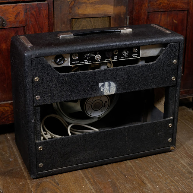
Here's a shot with an old Supro for scale. The amp is in pretty clean condition for its age, with minor edge-wear on the bottom of the cabinet and various prickings to the grill cloth. There are also the usual scratches near the input jacks on the front.
All of the pots operate smoothly and without noise.
The ground switch and auxiliary 2-prong outlet on the back of the amp no longer function (this is a good thing).
The original speaker cable is extant, even though the original speaker itself is long-gone.
Before I forget to mention them -- the tubes seem to be '90s Electro-Harmonix all-around and are working well.
Before I forget to mention them -- the tubes seem to be '90s Electro-Harmonix all-around and are working well.
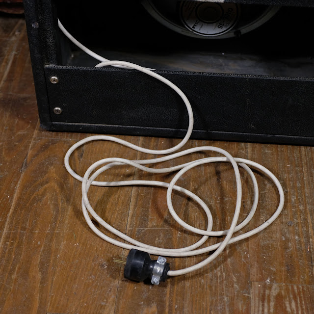
Here's the long, heavy-duty 3-prong cable that came with it.
A UK-made Celestion G10L-35 from the '80s is the noisemaker in this fella at the moment. It was in it when it came in.
Alright -- here are pics from the inside while I was sorting things out. This first one is of how I found it -- with the new 3-prong cord wired incorrectly. The fella who did the job just added a ground to the original circuit. You can see the hot and neutral wires (white/black) going to their original hookups at the accessory 2-prong outlet in the back while the green (ground) is at the chassis.
Those hot/neutrals then go to the ground switch (seen center) and then one side goes to the fuse and the other to the on/off switch.
In some of these photos you can see the big red blob capacitor under the ground switch -- this is the "death cap" in amp literature.
Here's the somewhat-tidy all-original wiring, otherwise.
Ok, now you can see my alterations to the circuit. I've cut the power cable down and then given myself more lead wire, knotted it once on the inside of the chassis, and then re-attached the strain relief at the point where it exits the chassis. That's double security, I suppose.
My next bit is to bypass the ground switch and accessory outlet entirely, so I simply clip their wires and remove them from the circuit. The old wire ends are tucked-in and taped-up, the "death cap" now does nothing, and now my neutral wire (white) runs directly to the fuse and the hot (black) runs to the switch. This is pretty bog-standard for "modern" wiring.
Well -- now she's all set to rock-away without fear of odd stuff happening electrocution-wise.


Comments